
Are you fascinated by the world of electronics and programming but feel intimidated to dive in? Many believe that tinkering with circuits and code requires years of engineering expertise. However, that’s a myth we’re about to bust! For car enthusiasts, tech hobbyists, and coding newcomers alike, the Arduino platform provides an accessible gateway to hands-on creation. If you’ve ever dreamt of building your own remote-controlled car, now is the perfect time to make that vision a reality. This guide will walk you through creating an Arduino Controlled Car Program and building the vehicle to bring it to life.
This project isn’t just a fun weekend activity; it’s a fantastic way to learn about electronics, programming, and mechanics in a practical and engaging way. We’ll leverage the simplicity of Arduino, readily available components, and a bit of creative problem-solving to construct a Bluetooth-controlled RC car from scratch. No prior experience is needed – just a willingness to learn and a bit of patience. We’ll break down each step, from assembling the chassis to writing the Arduino code, ensuring that even absolute beginners can follow along and succeed. Let’s get started and turn your desk into a DIY garage!
Project Overview: Arduino RC Car Construction
This project provides a comprehensive introduction to building an Arduino-based RC car. We prioritize simplicity and affordability, utilizing easily obtainable materials and focusing on clear, step-by-step instructions. The beauty of this project lies in its adaptability. While we provide a detailed blueprint, you’re encouraged to customize and innovate, making it truly your own. We’ll be using a power bank as our energy source – a cost-effective and reusable alternative to traditional batteries that many already have at home. This tutorial not only guides you through building this specific car but also imparts fundamental principles applicable to a wide range of DIY electronics projects.
Here’s a list of components you’ll need to gather for this exciting endeavor:
- Arduino UNO: The brains of our operation, the Arduino UNO microcontroller board will execute our program and control the car’s movements.
- Car Chassis Kit: A pre-made chassis with wheels, motors, and mounting hardware simplifies the mechanical assembly.
- Jumper Wires (Male-Male & Female-Male): These wires will be our electrical connectors, linking the various components.
- Electrical Insulation Tape: Essential for securing connections and preventing short circuits.
- Bluetooth Module (HC-06 or HC-05): This module enables wireless communication between your Android phone and the Arduino, allowing you to control the car remotely.
- DC Motor Controller (L298N): A crucial component that efficiently controls the speed and direction of the DC motors.
- Power Bank (with 2 USB outputs): Our portable and rechargeable power source for both the Arduino and motor controller.
- Piezo Buzzer: For adding fun sound effects to your RC car, enhancing the interactive experience.
- Android Mobile Phone: Used with a dedicated app to send control signals to the car via Bluetooth.
- PC with Arduino IDE Installed: You’ll need a computer to write, compile, and upload the arduino controlled car program to the Arduino board.
- ArduCar – Arduino RC Car Bluetooth Controller App: (Available on the Google Play Store) A ready-made Android application for controlling your Arduino RC car via Bluetooth.
Step 1: Assembling the Car Chassis
Let’s begin by putting together the physical foundation of our RC car – the chassis. If you purchased a chassis kit, it likely includes assembly instructions. However, we’ll cover the general steps here to ensure everyone is on the same page:
-
Motor Preparation: Gather the main chassis plate, motor mounting brackets (usually small plastic pieces – four in total, two for each motor), screws, brass spacers, nuts, the DC motors themselves, an old USB cable, and some jumper wires.
-
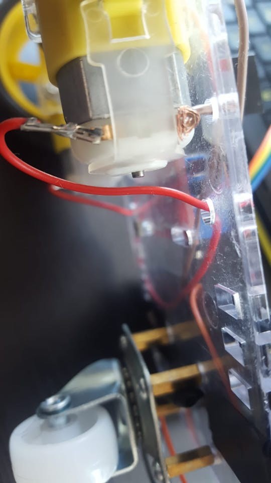
Wiring the Motors: Each motor needs to be connected to power. Attach a jumper wire to each terminal (pin) of both motors. Soldering provides the most secure connection, but if you don’t have a soldering iron, twisting the wires tightly around the pins will suffice for a beginner project.
-
USB Cable Prep for Power: Take an old or spare USB cable and cut off one end, leaving about 20cm (8 inches) of cable length.
-
Exposing Power Wires: Carefully strip a few centimeters of the outer insulation from the cut end of the USB cable to reveal the internal wires. You should typically find four or five wires inside. We are interested in the red wire (positive voltage) and the black wire (ground). Strip about 2-4 cm of insulation from the red and black wires. You can leave them as is, or for a more robust connection, twist or solder these to longer, stronger jumper wires.
-
Mounting the Motors: Position the motors onto the chassis frame. Use the plastic brackets (two per motor), screws, and nuts to secure them in place. Pay attention to the orientation of the motors; most small DC motors have a small dot on one side. Ensure these dots face inwards towards each other when both motors are mounted. This ensures consistent directionality.
- Installing the Supporting Wheel: Locate the four small holes arranged in a square pattern at the rear end of the chassis frame. These are for the supporting nylon wheel. Take the brass spacers and attach them to these holes using screws, positioning the spacers on the same side of the frame as the motors.
- Attaching the Nylon Wheel: Mount the nylon supporting wheel to the brass spacers using screws. This wheel provides stability and prevents the car from dragging.
- Wheel Installation: Push the wheels onto the motor shafts. Note the shape of the wheel hub and align it correctly with the motor shaft. You might encounter some resistance, but apply firm, gentle pressure until the wheels are securely in place.
- Mounting Electronic Components: Now, you can loosely mount the Arduino UNO board and the L298N DC motor controller onto the chassis frame. Use screws and nuts from your kit. You can use electrical tape to help secure wires and components as needed. Final mounting will be done after wiring.
Step 2: Wiring the Electronic Components
With the chassis assembled and components positioned, it’s time to connect everything electrically. Have your jumper wires (male-male and female-male) ready.
-
Motor to Motor Controller Connections: Connect the wires from the motors to the L298N DC motor controller. The L298N has screw terminals labeled OUT1, OUT2, OUT3, and OUT4. For each motor, connect one wire to an “OUT” terminal and the other to its corresponding ground terminal. A typical configuration is:
- OUT1: Left Motor (-) Ground wire
- OUT2: Left Motor (+) Power wire
- OUT3: Right Motor (+) Power wire
- OUT4: Right Motor (-) Ground wire
-
Arduino to Motor Controller (Control Signals): Now, we need to connect the Arduino to the motor controller to send control signals. We’ll use the IN1, IN2, IN3, and IN4 pins on the L298N. You’ll likely need female-male jumper wires for this. Connect them as follows:
- L298N IN1 to Arduino Digital Pin 5
- L298N IN2 to Arduino Digital Pin 6
- L298N IN3 to Arduino Digital Pin 10
- L298N IN4 to Arduino Digital Pin 11
-
Bluetooth Module Wiring: The Bluetooth module (HC-06 or HC-05) facilitates wireless control. It typically has four pins: VCC, GND, TXD, and RXD. Connect them to the Arduino as follows:
- Bluetooth VCC to Arduino 5V Pin (Power)
- Bluetooth GND to Arduino GND Pin (Ground)
- Bluetooth TXD to Arduino Digital Pin 0 (RXD – Receive Data)
- Bluetooth RXD to Arduino Digital Pin 1 (TXD – Transmit Data)
Notice that the TXD and RXD pins are cross-connected. This is because TX (transmit) needs to connect to RX (receive) for communication to occur.
-
Piezo Buzzer Connection (Optional): For sound effects, connect the piezo buzzer. It has two legs: a longer one (Anode +) and a shorter one (Cathode -).
- Piezo Buzzer Anode (Longer leg) to Arduino Digital Pin 3
- Piezo Buzzer Cathode (Shorter leg) to Arduino GND Pin (Ground)
While a 330 Ohm resistor between the piezo buzzer and the Arduino pin is often recommended to protect the buzzer, it can significantly reduce the sound volume. For this project, we will omit the resistor for louder sound, but be mindful of potential damage with prolonged use at high volumes.
- Powering the Motor Controller: Take the USB cable you prepared earlier. Connect the red wire (+) to the 12V terminal on the L298N motor controller and the black wire (-) to the GND terminal.
- Powering the Circuit: Finally, connect two USB cables to your power bank. One cable will power the Arduino (connect it to the Arduino’s USB port), and the other will power the motor controller (connected in the previous step). Mount the power bank securely to the chassis using electrical tape or another mounting method. Some power banks have a power button, so ensure it’s switched on to power the circuit.
With all components wired, we are ready to program the Arduino and bring our RC car to life with code.
Step 3: Programming Your Arduino Controlled Car
Now for the exciting part: writing and uploading the arduino controlled car program! You’ll need the Arduino IDE (Integrated Development Environment) installed on your computer. Download it for free from the official Arduino website.
- Arduino IDE Setup: Open the Arduino IDE. Go to “Tools” > “Board” and select “Arduino Uno” (or whichever Arduino board you are using). Then, go to “Tools” > “Port” and select the serial port that your Arduino is connected to. If you’re unsure which port, connect your Arduino to your computer via USB. The port option should become active; you might need to try different USB ports on your computer until the Arduino is recognized.
-
Uploading the Code: You have two options to get the code into the Arduino IDE:
a. Download and Open: Copy the code provided below. In the Arduino IDE, go to “File” > “New” and paste the code into the new sketch.
b. Copy and Paste: Select all the code below, copy it, and paste it into the Arduino IDE editor window.Before uploading, disconnect the Bluetooth module’s TX and RX wires from Arduino pins 0 and 1. These pins are used for communication during code upload, and having the Bluetooth module connected can interfere with the process.
Once the code is in the IDE and Bluetooth wires are disconnected, click the “Upload” button (the right arrow icon). The IDE will compile the code and upload it to your Arduino board. You’ll see a “Done uploading” message in the IDE when the process is complete.
#define in1 5
#define in2 6
#define in3 10
#define in4 11
int state;
int piezo = 3;

void setup() {
  pinMode(in1, OUTPUT);
  pinMode(in2, OUTPUT);
  pinMode(in3, OUTPUT);
  pinMode(in4, OUTPUT);
  pinMode(piezo,OUTPUT);
  Serial.begin(9600);
}

void loop() {
  if (Serial.available() > 0) {
    state = Serial.read();
    Stop();
    switch (state) {
      case 'F': forward(); soundFX(3000.0,30+400*(1+sin(millis()/5000))); break;
      case 'G': forwardleft(); soundFX(3000.0,60); break;
      case 'D': forwardright(); soundFX(3000.0,60); break;
      case 'N': backright(); soundFX(3000.0,30+100*(1+sin(millis()/2500))); break;
      case 'C': backleft(); soundFX(3000.0,30+100*(1+sin(millis()/2500))); soundFX(3000.0,30+100*(1+sin(millis()/2500))); soundFX(3000.0,30+100*(1+sin(millis()/2500))); soundFX(3000.0,30+100*(1+sin(millis()/2500))); break;
      case 'B': back(); soundFX(3000.0,30+200*(1+sin(millis()/2500))); soundFX(3000.0,30+200*(1+sin(millis()/2500))); soundFX(3000.0,30+200*(1+sin(millis()/2500))); soundFX(3000.0,30+200*(1+sin(millis()/2500))); break;
      case 'L': left(); soundFX(3000.0,60); soundFX(3000.0,60); soundFX(3000.0,60); soundFX(3000.0,60); break;
      case 'R': right(); soundFX(3000.0,60); soundFX(3000.0,60); soundFX(3000.0,60); soundFX(3000.0,60); break;
      case 'H': soundFX(3000.0,30+200*(1+sin(millis()/2500))); soundFX(3000.0,60); soundFX(3000.0,30+200*(1+sin(millis()/2500))); soundFX(3000.0,60);
    }
  }
}

void forward() {
  analogWrite(in1, 255);
  analogWrite(in3, 255);
}

void forwardleft() {
  analogWrite(in1, 50);
  analogWrite(in3, 255);
}

void forwardright() {
  analogWrite(in1, 255);
  analogWrite(in3, 50);
}

void back() {
  analogWrite(in2, 255);
  analogWrite(in4, 255);
}

void backright() {
  analogWrite(in2, 50);
  analogWrite(in4, 255);
}

void backleft() {
  analogWrite(in2, 50);
  analogWrite(in4, 50);
}

void left() {
  analogWrite(in4, 255);
  analogWrite(in1, 255);
}

void right() {
  analogWrite(in3, 255);
  analogWrite(in2, 255);
}

void Stop() {
  analogWrite(in1, 0);
  analogWrite(in2, 0);
  analogWrite(in3, 0);
  analogWrite(in4, 0);
}

void soundFX(float amplitude,float period){
  int uDelay=2+amplitude+amplitude*sin(millis()/period);
  for(int i=0;i<200;i++){
    digitalWrite(piezo, HIGH);
    delayMicroseconds(uDelay);
    digitalWrite(piezo, LOW);
    delayMicroseconds(uDelay);
  }
}- Reconnect Bluetooth and Power: After successful code upload, reconnect the Bluetooth module’s TX and RX wires to Arduino pins 0 and 1. Also, reconnect the USB cable from the Arduino to the power bank to power the circuit.
- Android App and Control: Download the “ArduCar – Arduino RC Car Bluetooth Controller” app from the Google Play Store onto your Android phone. Launch the app, pair your phone with the Bluetooth module (usually named HC-05 or HC-06 – default password might be 1234 or 0000), and you should now be able to control your Arduino RC car wirelessly!
You can also explore other Arduino RC car control apps on the Play Store or even develop your own application if you’re feeling ambitious! The key is to ensure the app sends compatible serial commands to the Bluetooth module, which are then interpreted by your arduino controlled car program.
Congratulations! You have successfully built and programmed your own Arduino controlled RC car. Enjoy driving it around and experimenting with modifications and enhancements!
Step 4: Understanding the Arduino Code and Bluetooth Configuration
For those eager to understand the inner workings of the arduino controlled car program, let’s delve into the code and briefly touch upon Bluetooth module configuration.
Arduino Code Breakdown
The code we uploaded is written in a simplified C/C++ based language used by the Arduino IDE. Every Arduino program has two essential sections:
-
void setup() { }: This section runs only once when the Arduino board starts up. It’s used to initialize settings, like defining pin modes.void setup() { pinMode(in1, OUTPUT); pinMode(in2, OUTPUT); pinMode(in3, OUTPUT); pinMode(in4, OUTPUT); pinMode(piezo,OUTPUT); Serial.begin(9600); }pinMode(in1, OUTPUT);etc.: These lines configure digital pins 5, 6, 10, 11 (namedin1,in2,in3,in4respectively) and pin 3 (piezo) as OUTPUT pins. This means the Arduino will send signals out of these pins to control other components (motor controller and buzzer).Serial.begin(9600);: This initializes serial communication at a baud rate of 9600 bits per second. This is the communication channel used to receive commands from the Bluetooth module. 9600 is a common and reliable baud rate for Bluetooth communication.
-
void loop() { }: This section runs continuously in a loop after thesetup()function completes. It’s the main part of your program where the Arduino constantly checks for inputs and executes actions.void loop() { if (Serial.available() > 0) { state = Serial.read(); Stop(); switch (state) { // ... (cases for different commands) ... } } }if (Serial.available() > 0): This checks if there is any data available to be read from the serial port (i.e., from the Bluetooth module).state = Serial.read();: If data is available, it reads the incoming byte and stores it in thestatevariable. Thisstatevariable will hold the command character sent from the Android app.Stop();: This function (defined later in the code) immediately stops the car motors before executing any new command, ensuring smooth transitions.switch (state) { ... }: Thisswitchstatement checks the value of thestatevariable (the command received). Based on the character received (‘F’, ‘B’, ‘L’, ‘R’, etc.), it executes differentcaseblocks, which call functions to control the car’s movement (e.g.,forward(),left(),back()).soundFX(...): These functions (also defined later) trigger sound effects from the piezo buzzer, adding an interactive element to the car.break;: Thebreak;statement at the end of eachcaseblock prevents the code from “falling through” to the next case.
-
Pin and Variable Definitions: Before
void setup(), we have lines like#define in1 5.#define in1 5 #define in2 6 #define in3 10 #define in4 11 int state; int piezo = 3;#define in1 5: This is a preprocessor directive that defines a symbolic namein1and assigns it the value 5. Whereverin1is used in the code, the Arduino IDE will replace it with the number 5. This makes the code more readable and easier to modify. We do this for all the motor control pins and the piezo buzzer pin.int state;: This declares an integer variable namedstate. This variable will store the command character received via Bluetooth.int piezo = 3;: This declares an integer variable namedpiezoand initializes it with the value 3. This variable represents the Arduino pin connected to the piezo buzzer.
-
Movement Functions: Functions like
forward(),back(),left(),right(),forwardleft(),forwardright(),backleft(),backright(), andStop()control the motors.void forward() { analogWrite(in1, 255); analogWrite(in3, 255); } void Stop() { analogWrite(in1, 0); analogWrite(in2, 0); analogWrite(in3, 0); analogWrite(in4, 0); } // ... other movement functions ...void forward() { ... }: Theforward()function sets thein1andin3pins toanalogWrite(..., 255).analogWrite()is used to control the speed of the motors. A value of 255 represents full speed in one direction, while 0 represents no speed. By controlling the voltage to different motor inputs viain1toin4, we control the direction and speed.void Stop() { ... }: TheStop()function sets all motor control pins toanalogWrite(..., 0), effectively stopping both motors.
-
Sound Effects Function: The
soundFX()function generates simple sci-fi-like sound effects using the piezo buzzer.void soundFX(float amplitude,float period){ int uDelay=2+amplitude+amplitude*sin(millis()/period); for(int i=0;i<200;i++){ digitalWrite(piezo, HIGH); delayMicroseconds(uDelay); digitalWrite(piezo, LOW); delayMicroseconds(uDelay); } }void soundFX(float amplitude, float period) { ... }: This function takesamplitudeandperiodas parameters to control the frequency and duration of the sound. It usesdigitalWrite()to rapidly turn the piezo buzzer ON and OFF, creating sound waves. Thesin(millis()/period)part introduces a changing frequency, creating a more interesting sound.
Bluetooth Module Configuration (Optional)
HC-05 and HC-06 Bluetooth modules come with default settings (like baud rate, name, and password). For basic use, the default settings are usually sufficient. However, if you need to customize these settings (e.g., change the Bluetooth name or password), you can configure the module using AT commands sent via the Arduino IDE serial monitor.
Configuration typically involves connecting the Bluetooth module to the Arduino in a specific configuration (often requiring disconnecting it from the RX/TX pins used for normal communication and potentially using different pins). You then need to upload a special Arduino sketch that allows you to send AT commands through the serial monitor to the Bluetooth module. There are numerous online tutorials detailing this process if you wish to explore Bluetooth module configuration further.
This detailed explanation should give you a solid understanding of the arduino controlled car program and how it works. Feel free to experiment with the code, modify it, add new features, and continue to explore the exciting world of Arduino and DIY electronics!