
Are you fascinated by robotics and remote control cars? Have you ever wanted to understand the magic behind how these devices work? You might think that delving into electronics and programming is daunting, reserved only for seasoned engineers. But the truth is, with the right tools and guidance, anyone can embark on this exciting journey. As a car enthusiast and coding lover, I can tell you that combining these passions is incredibly rewarding. If you had an RC car as a kid and dreamt of building your own, now is the perfect time to turn that dream into reality. With an Arduino kit and some basic components, you can create a custom RC car and learn valuable programming skills along the way.
This guide will walk you through building an Arduino-powered RC car from scratch. No prior experience in programming, Arduino, or electronics is needed! While some background knowledge might be helpful, these instructions are designed to be easy to follow for anyone. We’ll use readily available and affordable materials, focusing on a practical, hands-on approach. This project not only teaches you the fundamentals of building an RC car but also provides a solid foundation for various other electronics and programming projects. So, let’s get started and bring your own Arduino RC car to life!
For this project, we’ll utilize common and easily obtainable components. You might even have some of these lying around from old electronics! Feel free to adapt and get creative with your materials, but here’s a list of what we’ll be using:
- Arduino UNO board
- RC car chassis kit (including wheels and motors)
- Jumper wires (male-male and female-male)
- Electrical tape
- Bluetooth module (HC-06 or HC-05)
- DC motor controller (L298N)
- Power bank with dual USB outputs
- Piezo buzzer
- Android smartphone
- Computer with Arduino IDE installed
- ArduCar – Arduino RC Car Bluetooth Controller App
Step 1: Assembling the RC Car Chassis
Let’s begin by putting together the foundation of our RC car – the chassis. If you purchased a kit, it likely includes assembly instructions. However, here’s a step-by-step guide to ensure you get it right:
- Prepare the Motor Mounts: Gather the main chassis frame, four small plastic motor brackets (two for each motor), screws, brass spacers, nuts, motors, an old USB cable, and four jumper wires.
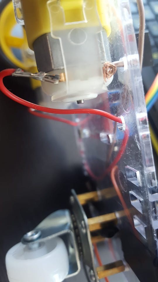
- Connect Wires to Motors: Attach a wire to each terminal of the motors. Soldering is ideal for a robust connection, but if you don’t have a soldering iron, twisting the wires securely around the terminals will also work for beginners.
Image: Close-up of a DC motor with wires attached to its terminals, ready for chassis mounting.
- Prepare the USB Power Cable: Take an old USB cable and cut off one end, leaving about 20cm (8 inches) of cable length.
- Expose Power Wires: Carefully strip a few centimeters of the cable’s outer insulation to reveal the internal wires. You should see 4 or 5 wires, but we only need the red (positive) and black (ground) wires. Strip about 2-4 cm of insulation from the red and black wires. For a stronger connection, you can twist or solder these wires to longer, more durable jumper wires.
Image: A USB cable with its outer jacket stripped, exposing the red and black power wires.
- Mount Motors to Chassis: Attach the motors to the chassis frame using the plastic brackets, screws, and nuts. Note the small dot on one side of each motor. Ensure these dots face inward towards each other when both motors are mounted. This orientation is important for correct motor direction later on.
Image: RC car chassis with DC motors securely mounted using brackets and screws.
- Install Supporting Wheel Spacers: Locate the four small holes in a square pattern at the end of the chassis frame. Attach brass spacers to these holes using screws, positioning the spacers on the same side of the frame as the motors.
- Mount Supporting Wheel: Attach the nylon supporting wheel to the brass spacers using screws. This wheel provides stability and balance to the RC car.
Image: Close-up showing the nylon supporting wheel mounted to the chassis using brass spacers.
- Attach Wheels and Mount Electronic Boards: Install the main wheels onto each motor shaft. You might encounter some resistance due to the tight fit, but apply gentle, firm pressure to push them into place. Now, mount the Arduino UNO board and the L298N DC motor controller onto the chassis frame. Use leftover screws and nuts from the kit. Secure any exposed wires with electrical tape to prevent shorts and ensure a clean setup.
Image: Top view of the assembled chassis with motors, wheels, Arduino UNO, and L298N motor controller mounted.
Step 2: Wiring the Electronic Components
With the chassis assembled and the electronic boards mounted, it’s time to connect everything using jumper wires. Prepare both male-male and female-male jumper wires for this step.
-
Connect Motors to Motor Controller: Attach the wires from the motors to the L298N DC motor controller. The lower pins (closer to the ground) are generally considered positive (+), and the upper pins (closer to the frame) are negative (GND). Follow this wiring scheme:
- OUT1: Left motor (-) GND wire
- OUT2: Left motor (+) wire
- OUT3: Right motor (+) wire
- OUT4: Right motor (-) GND wire
Image: Wiring diagram illustrating the connection of motor wires to the OUT terminals of the L298N motor controller.
-
Connect Arduino to Motor Controller: Now, we’ll connect the Arduino UNO to the L298N motor controller to send control signals. Use female-male jumper wires for these connections. If you don’t have them, you can modify male-male wires or solder wires directly. Connect the following pins:
- IN1: Arduino Digital Pin 5
- IN2: Arduino Digital Pin 6
- IN3: Arduino Digital Pin 10
- IN4: Arduino Digital Pin 11
-
Connect Bluetooth Module: The Bluetooth module (HC-06 or HC-05) enables wireless control of your RC car. These modules typically have four pins labeled VCC, GND, TXD, and RXD. Use female-male jumper wires to connect them as follows:
- VCC: Arduino 5V Power Pin
- GND: Arduino GND (Ground) Pin
- TXD: Arduino Digital Pin 0 (RXD) – Note the cross-connection: TX to RX
- RXD: Arduino Digital Pin 1 (TXD) – Note the cross-connection: RX to TX
Data is exchanged between the Arduino and the Bluetooth module, which is why the TX and RX pins are cross-connected.
Image: Wiring diagram showing the connection of the Bluetooth module to the Arduino UNO board, highlighting the TX/RX cross-connection.
-
Connect Piezo Buzzer (Optional): A piezo buzzer adds sound effects to your RC car. It has two legs: a longer anode (+) and a shorter cathode (-). While a 330 Ohm resistor is recommended for sensitive piezo buzzers, it’s often skipped in basic projects for louder sound. Connect the buzzer as follows:
- Anode (+, longer leg): Arduino Digital Pin 3
- Cathode (-, shorter leg): Arduino GND (Ground) Pin
Image: Wiring diagram depicting the piezo buzzer connection to the Arduino, showing anode and cathode legs.
-
Power the Motor Controller: Take the USB cable you prepared earlier (with red and black wires) and connect them to the L298N motor controller to provide power to the motors:
- Red wire (+): L298N 12V Input
- Black wire (-): L298N GND
-
Power the Entire Circuit: Finally, connect two USB cables to your power bank. Plug one into the Arduino UNO to power the microcontroller and sensors. Plug the other USB cable (connected to the motor controller) into the power bank as well. Mount the power bank to the chassis using electrical tape or another secure method. Some power banks have a power button that needs to be switched on to activate the power output.
Image: Comprehensive circuit diagram showcasing all component connections: Arduino, motor controller, Bluetooth module, piezo buzzer, and power supply.
With all components wired up, we’re ready to program the Arduino and control our RC car!
Step 3: Programming Your Arduino RC Car
Now comes the exciting part – bringing your RC car to life with code! You’ll need to upload code to the Arduino board and install a control application on your Android phone.
- Install Arduino IDE: Download and install the Arduino IDE (Integrated Development Environment) from the official Arduino website (https://www.arduino.cc/). This software allows you to write, compile, and upload code to your Arduino board.
- Configure Arduino IDE: Open the Arduino IDE. Go to “Tools” > “Board:” and select “Arduino Uno” (or your specific Arduino board). Then, go to “Tools” > “Port:” and select the port your Arduino is connected to. If you’re unsure which port, connect your Arduino to your computer via USB. The port option should become active; try different USB ports until you find the correct one.
Image: Screenshot of the Arduino IDE showing the “Tools” menu expanded, highlighting the “Board” and “Port” selections.
-
Upload the Arduino Code: You have two options for uploading the code:
- Download and Open Code File: Download the provided Arduino code file (if available). Open the file in the Arduino IDE.
- Copy and Paste Code: Copy the code provided below and paste it into a new Arduino IDE window (File > New).
Important: Before uploading, disconnect the Bluetooth module’s RX (Digital 0) and TX (Digital 1) wires from the Arduino. These pins are used for communication with your computer during code upload, and interference from the Bluetooth module can cause upload errors.
Once you have the code in the IDE, click the “Upload” button (usually a right-arrow icon). Ensure your Arduino board is connected to your computer via USB and the correct port is selected.
#define in1 5 #define in2 6 #define in3 10 #define in4 11 int state; int piezo = 3; void setup() { pinMode(in1, OUTPUT); pinMode(in2, OUTPUT); pinMode(in3, OUTPUT); pinMode(in4, OUTPUT); pinMode(piezo,OUTPUT); Serial.begin(9600); } void loop() { if (Serial.available() > 0) { state = Serial.read(); Stop(); switch (state) { case 'F': forward(); soundFX(3000.0,30+400*(1+sin(millis()/5000))); break; case 'G': forwardleft(); soundFX(3000.0,60); break; case 'D': forwardright(); soundFX(3000.0,60); break; case 'N': backright(); soundFX(3000.0,30+100*(1+sin(millis()/2500))); break; case 'C': backleft(); soundFX(3000.0,30+100*(1+sin(millis()/2500))); soundFX(3000.0,30+100*(1+sin(millis()/2500))); soundFX(3000.0,30+100*(1+sin(millis()/2500))); soundFX(3000.0,30+100*(1+sin(millis()/2500))); break; case 'B': back(); soundFX(3000.0,30+200*(1+sin(millis()/2500))); soundFX(3000.0,30+200*(1+sin(millis()/2500))); soundFX(3000.0,30+200*(1+sin(millis()/2500))); soundFX(3000.0,30+200*(1+sin(millis()/2500))); break; case 'L': left(); soundFX(3000.0,60); soundFX(3000.0,60); soundFX(3000.0,60); soundFX(3000.0,60); break; case 'R': right(); soundFX(3000.0,60); soundFX(3000.0,60); soundFX(3000.0,60); soundFX(3000.0,60); break; case 'H': soundFX(3000.0,30+200*(1+sin(millis()/2500))); soundFX(3000.0,60); soundFX(3000.0,30+200*(1+sin(millis()/2500))); soundFX(3000.0,60); break; } } } void forward() { analogWrite(in1, 255); analogWrite(in3, 255); } void forwardleft() { analogWrite(in1, 50); analogWrite(in3, 255); } void forwardright() { analogWrite(in1, 255); analogWrite(in3, 50); } void back() { analogWrite(in2, 255); analogWrite(in4, 255); } void backright() { analogWrite(in2, 50); analogWrite(in4, 255); } void backleft() { analogWrite(in2, 50); analogWrite(in4, 50); } void left() { analogWrite(in4, 255); analogWrite(in1, 255); } void right() { analogWrite(in3, 255); analogWrite(in2, 255); } void Stop() { analogWrite(in1, 0); analogWrite(in2, 0); analogWrite(in3, 0); analogWrite(in4, 0); } void soundFX(float amplitude,float period){ int uDelay=2+amplitude+amplitude*sin(millis()/period); for(int i=0;i<amplitude;i++) { digitalWrite(piezo, HIGH); delayMicroseconds(uDelay); digitalWrite(piezo, LOW); delayMicroseconds(uDelay); } } -
Reconnect Bluetooth Module: After successful code upload, reconnect the Bluetooth module’s RX (Digital 0) and TX (Digital 1) wires to the Arduino. Also, reconnect the USB cable from the Arduino to your power bank.
-
Install Android Control App: Download and install the “ArduCar – Arduino RC Car Bluetooth Controller” app from the Google Play Store:
Image: Google Play Store badge linking to the ArduCar Android application for controlling the RC car.
Launch the app, connect to your Bluetooth module (you may need to pair it in your phone’s Bluetooth settings first, usually with a default password like “1234” or “0000”), and you’re ready to drive your Arduino RC car!
Image: A horizontal shot of the completed Arduino RC car in motion, showcasing its functionality.
Congratulations! You’ve built and programmed your own Bluetooth-controlled Arduino RC car. Have fun experimenting and driving your creation! For those interested in diving deeper, let’s explore the code and Bluetooth module configuration in more detail.
Step 4: Understanding the Arduino Code and Bluetooth Configuration
For those eager to understand the inner workings of the code and explore Bluetooth module customization, this section provides a detailed explanation.
Arduino Code Breakdown
Arduino code is based on a simplified version of C/C++. If you’re familiar with these languages, you’ll recognize the structure. If not, don’t worry – the basics are easy to grasp. Every Arduino program has two fundamental sections:
-
void setup() { }: This section runs only once when the Arduino board starts. It’s used to configure pins and initialize settings.In our code:
void setup() { pinMode(in1, OUTPUT); pinMode(in2, OUTPUT); pinMode(in3, OUTPUT); pinMode(in4, OUTPUT); pinMode(piezo,OUTPUT); Serial.begin(9600); }-
pinMode(in1, OUTPUT);and similar lines:pinMode()sets the mode of a digital pin.OUTPUTmeans we’re sending signals from the Arduino to control components connected to these pins (in our case, the motor controller and piezo buzzer).in1,in2,in3,in4, andpiezoare names we’ve assigned to specific Arduino pins (Digital Pins 5, 6, 10, 11, and 3, respectively) at the beginning of the code using#define. -
Serial.begin(9600);: This line initializes serial communication at a baud rate of 9600 bits per second. Serial communication is used for sending and receiving data via the Bluetooth module. 9600 is a common and reliable baud rate for Bluetooth modules.
-
-
void loop() { }: This section runs continuously, repeatedly executing the code within its curly braces. This is where the main control logic of your program resides.void loop() { if (Serial.available() > 0) { state = Serial.read(); Stop(); switch (state) { // ... (cases for different commands) ... } } }-
if (Serial.available() > 0) { ... }: Thisifstatement checks if there is any data available to be read from the serial port (i.e., from the Bluetooth module).Serial.available()returns the number of bytes of data waiting to be read. If it’s greater than 0, it means the Bluetooth module has sent data. -
state = Serial.read();: This line reads the first byte of incoming serial data and stores it in thestatevariable. Thestatevariable will hold the command character sent from your Android app (like ‘F’ for forward, ‘L’ for left, etc.). -
Stop();: This line calls theStop()function, which immediately stops the RC car’s motors. This ensures the car stops before executing a new command. -
switch (state) { ... }: Theswitchstatement allows you to execute different blocks of code based on the value of thestatevariable. Eachcasecorresponds to a different command character sent from the Bluetooth app.case 'F': forward(); soundFX(...); break;: Ifstateis ‘F’ (forward command), it calls theforward()function to move the car forward and thesoundFX()function to play a sound effect.break;exits theswitchstatement after executing the corresponding case. Similarcaseblocks exist for other commands like ‘G’ (forward-left), ‘D’ (forward-right), ‘B’ (backward), ‘L’ (left), ‘R’ (right), etc., each calling specific motor control functions and sound effects.
-
-
Function Definitions: Functions are blocks of reusable code that perform specific tasks. In our code, we have functions for each car movement and sound effects defined after the
loop()function:-
void forward() { ... },void back() { ... },void left() { ... },void right() { ... },void forwardleft() { ... },void forwardright() { ... },void backleft() { ... },void backright() { ... },void Stop() { ... }: These functions control the motors usinganalogWrite().analogWrite(pin, value): This function sends a PWM (Pulse Width Modulation) signal to a specified pin, effectively controlling the speed of the motors.pinis the motor control pin (e.g.,in1,in3).valueis a number between 0 and 255, where 0 is stopped and 255 is full speed. By controlling theanalogWritevalues for different motor control pins (in1, in2, in3, in4), we can control the direction and speed of each motor, and thus the movement of the RC car.
-
void soundFX(float amplitude, float period) { ... }: This function generates a sound effect using the piezo buzzer. It takesamplitudeandperiodas parameters to control the tone and duration of the sound. The code within this function usesdigitalWrite()anddelayMicroseconds()to create sound waves at the piezo buzzer.digitalWrite(piezo, HIGH)anddigitalWrite(piezo, LOW): These lines turn the piezo buzzer ON and OFF rapidly to generate sound.delayMicroseconds(uDelay): This function pauses the program execution for a specified number of microseconds, controlling the frequency of the sound wave.
-
Bluetooth Module Configuration (Optional)
HC-05 and HC-06 Bluetooth modules come with default settings (like baud rate, name, and password). For most basic projects, the default settings work fine. However, if you want to customize your Bluetooth module (e.g., change its name or password), you can configure it using AT commands through the Arduino IDE.
Note: Configuring Bluetooth modules can be slightly more advanced and may require additional research and potentially the use of voltage dividers to protect the Bluetooth module’s 3.3V logic level from Arduino’s 5V output. Numerous online tutorials detail the Bluetooth module configuration process using AT commands and Arduino. Search online for “HC-06 AT commands Arduino” or “HC-05 AT commands Arduino” for detailed guides if you wish to explore this further.
We hope this detailed explanation enhances your understanding of the Arduino code and provides a stepping stone for further exploration. Feel free to experiment with the code, modify sound effects, or add new features to your Arduino RC car project! Share your creations and modifications in the comments below – we’d love to see what you build!