
Are you fascinated by remote control cars and eager to dive into the world of programming and electronics? You might think you need to be an expert engineer to create your own custom RC car, but that’s far from the truth! This guide will walk you through building an Arduino-powered RC car from the ground up, even if you have no prior experience with Arduino, programming, or electronics. We’ll break down each step, from assembling the chassis to writing the Arduino code, making it a fun and educational project for beginners and hobbyists alike. Get ready to bring your childhood dreams to life and learn Arduino Programming For Rc Car control!
Getting Started: What You’ll Need
One of the great things about this project is its accessibility. We’ll use readily available components and focus on simplicity. You might even have some of these items lying around already! Here’s a list of materials you’ll need to gather:
- Arduino UNO: The brain of your RC car, easy to program and perfect for beginners.
- RC Car Chassis Kit: Choose a kit with wheels, motors, and a basic chassis frame. This simplifies the mechanical build.
- Jumper Wires (Male-Male & Female-Male): For connecting electronic components.
- Electrical Insulation Tape: For tidy wiring and insulation.
- Bluetooth Module (HC-06 or HC-05): Allows wireless control of your car via Bluetooth.
- DC Motor Controller (L298N): Essential for controlling the speed and direction of the DC motors.
- Power Bank (with 2 USB outputs): A convenient and rechargeable power source for your project.
- Piezo Buzzer: For adding fun sound effects to your RC car.
- Android Mobile Phone: To install the control application.
- PC with Arduino IDE: To program your Arduino board.
- ArduCar – Arduino RC Car Bluetooth Controller App: A ready-made Android app for controlling your RC car (or you can explore others!).
Step 1: Assembling the RC Car Chassis
Let’s start by putting together the physical foundation of our RC car – the chassis. Most chassis kits come with instructions, but here’s a step-by-step guide to help you along:
-
Prepare the Components: Gather the chassis frame, motor mounting brackets (usually plastic), screws, brass spacers, nuts, DC motors, a spare USB cable, and jumper wires.
-
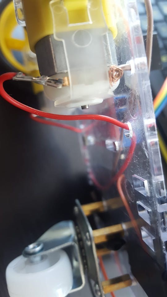
Connect Wires to Motors: Attach a jumper wire to each terminal of the DC motors. Soldering provides a robust connection, but if you don’t have a soldering iron, you can securely twist or “knot” the wires to the motor pins.
-
Prepare the USB Cable for Power: Take an old USB cable and cut off one end, leaving about 20cm (8 inches) of cable. Carefully strip a few centimeters of the outer insulation to expose the internal wires. You should see several wires inside, but we only need the red (positive) and black (ground) wires. Strip about 2-4cm of insulation from these red and black wires. Reinforce the connection by twisting or soldering these to longer, stronger jumper wires for a more reliable power supply.
-
Mount Motors to Chassis: Attach the DC motors to the chassis frame using the plastic brackets and screws. Most motors have a small dot on one side. Ensure these dots face inwards when mounting the motors opposite each other. This helps with consistent motor direction.
-
Install Supporting Wheel: Locate the four small holes in a square pattern at the rear of the chassis frame. These are for the supporting nylon wheel. Use brass spacers and screws to mount the spacers to these holes, ensuring they are on the same side of the frame as the motors. Then, attach the nylon supporting wheel to the spacers with screws.
-
Attach Wheels to Motors: Push the wheels onto the motor shafts. You might encounter some resistance, but gently apply even pressure until they are securely in place. Note the shape inside the wheel hub to ensure proper alignment.
- Mount Arduino and Motor Controller: Position the Arduino UNO board and the L298N DC motor controller on the chassis frame. Use screws and nuts (some kits provide extras) to secure them. Use electrical tape to insulate any exposed wires and ensure components are firmly mounted.
Step 2: Wiring the Electronics
With the chassis assembled and components mounted, it’s time to connect everything. Clear wiring is crucial for a functional and reliable RC car. Use your jumper wires and follow these steps carefully:
-
Connect Motors to Motor Controller: Attach the wires from your motors to the L298N DC motor controller. The L298N has terminals labeled OUT1, OUT2, OUT3, and OUT4. Connect them as follows, assuming the pins closer to the edge are negative (-) and the inner pins are positive (+):
- OUT1: Left Motor (-) Ground wire
- OUT2: Left Motor (+) Power wire
- OUT3: Right Motor (+) Power wire
- OUT4: Right Motor (-) Ground wire
-
Connect Arduino to Motor Controller (Control Signals): Now, we need to send control signals from the Arduino to the motor controller. Use female-male jumper wires to connect the following pins on the L298N to the Arduino:
- L298N IN1: Arduino Digital Pin 5
- L298N IN2: Arduino Digital Pin 6
- L298N IN3: Arduino Digital Pin 10
- L298N IN4: Arduino Digital Pin 11
-
Connect Bluetooth Module: The Bluetooth module enables wireless control. Connect your HC-06 or HC-05 Bluetooth module to the Arduino using female-male jumper wires:
- Bluetooth VCC: Arduino 5V Pin (Power)
- Bluetooth GND: Arduino GND Pin (Ground)
- Bluetooth TXD: Arduino Digital Pin 0 (RXD – Receive Data)
- Bluetooth RXD: Arduino Digital Pin 1 (TXD – Transmit Data)
Note the cross-wiring: Bluetooth TXD to Arduino RXD and vice versa. This is essential for serial communication.
-
Connect Piezo Buzzer (Optional Sound Effects): For sound effects, connect the piezo buzzer:
- Piezo Buzzer Anode (Longer Leg, +): Arduino Digital Pin 3
- Piezo Buzzer Cathode (Shorter Leg, -): Arduino GND Pin (Ground)
While a 330 Ohm resistor is often recommended for piezo buzzers to limit current, it can reduce volume. For this project, connecting directly can work, but consider a resistor for more sensitive buzzers or prolonged use.
-
Powering the Motor Controller: Take the USB cable you prepared earlier. Connect the red (+) wire to the 12V terminal and the black (-) wire to the GND terminal on the L298N motor controller.
-
Powering the Arduino and Final Connections: You’ll use the power bank to supply power. Connect one USB output of the power bank to the Arduino UNO using a standard USB cable. Connect the other USB output to the USB cable connected to the L298N motor controller. Finally, mount the power bank securely to the chassis using electrical tape or another mounting method. Some power banks have power buttons, so ensure it’s switched on to power the circuit.
Step 3: Arduino Programming for RC Car Control
Now for the exciting part – programming your Arduino to control the RC car! You’ll need the Arduino IDE (Integrated Development Environment) software installed on your computer. Download it for free from the official Arduino website.
- Set up Arduino IDE: Open the Arduino IDE. Go to Tools > Board and select Arduino UNO. Then, go to Tools > Port and choose the serial port that your Arduino board is connected to. The port will usually appear after you connect your Arduino to your computer via USB. If you’re unsure, try different ports until you can upload code.
-
Upload the Arduino Code: You have two options for getting the code onto your Arduino:
a) Download and Open: Download the provided Arduino code file (if available with this tutorial). Open it in the Arduino IDE.
b) Copy and Paste: Copy the code provided below and paste it into a new Arduino IDE sketch (File > New).Important: Disconnect the Bluetooth module’s TX and RX wires (Digital Pins 0 and 1) from the Arduino before uploading the code. These pins are used for communication with your computer during upload, and interference from the Bluetooth module can cause upload errors. Reconnect them after uploading is complete.
Click the Upload button (right arrow icon) in the Arduino IDE to compile and upload the code to your Arduino board. Ensure your Arduino is connected to your computer via USB and the correct port is selected.
#define in1 5
#define in2 6
#define in3 10
#define in4 11
int state;
int piezo = 3;

void setup() {
  pinMode(in1, OUTPUT);
  pinMode(in2, OUTPUT);
  pinMode(in3, OUTPUT);
  pinMode(in4, OUTPUT);
  pinMode(piezo,OUTPUT);
  Serial.begin(9600);
}

void loop() {
  if (Serial.available() > 0) {
    state = Serial.read();
    Stop();
    switch (state) {
      case 'F': forward(); soundFX(3000.0,30+400*(1+sin(millis()/5000))); break;
      case 'G': forwardleft(); soundFX(3000.0,60); break;
      case 'D': forwardright(); soundFX(3000.0,60); break;
      case 'N': backright(); soundFX(3000.0,30+100*(1+sin(millis()/2500))); break;
      case 'C': backleft(); soundFX(3000.0,30+100*(1+sin(millis()/2500)));
                   soundFX(3000.0,30+100*(1+sin(millis()/2500)));
                   soundFX(3000.0,30+100*(1+sin(millis()/2500)));
                   soundFX(3000.0,30+100*(1+sin(millis()/2500)));
                   break;
      case 'B': back(); soundFX(3000.0,30+200*(1+sin(millis()/2500)));
                   soundFX(3000.0,30+200*(1+sin(millis()/2500)));
                   soundFX(3000.0,30+200*(1+sin(millis()/2500)));
                   soundFX(3000.0,30+200*(1+sin(millis()/2500)));
                   break;
      case 'L': left(); soundFX(3000.0,60);
                   soundFX(3000.0,60);
                   soundFX(3000.0,60);
                   soundFX(3000.0,60);
                   break;
      case 'R': right(); soundFX(3000.0,60);
                   soundFX(3000.0,60);
                   soundFX(3000.0,60);
                   soundFX(3000.0,60);
                   break;
      case 'H': soundFX(3000.0,30+200*(1+sin(millis()/2500)));
                   soundFX(3000.0,60);
                   soundFX(3000.0,30+200*(1+sin(millis()/2500)));
                   soundFX(3000.0,60);
    }
  }
}

void forward() {
  analogWrite(in1, 255);
  analogWrite(in3, 255);
}

void forwardleft() {
  analogWrite(in1, 50);
  analogWrite(in3, 255);
}

void forwardright() {
  analogWrite(in1, 255);
  analogWrite(in3, 50);
}

void back() {
  analogWrite(in2, 255);
  analogWrite(in4, 255);
}

void backright() {
  analogWrite(in2, 50);
  analogWrite(in4, 255);
}

void backleft() {
  analogWrite(in2, 50);
  analogWrite(in4, 50);
}

void left() {
  analogWrite(in4, 255);
  analogWrite(in1, 255);
}

void right() {
  analogWrite(in3, 255);
  analogWrite(in2, 255);
}

void Stop() {
  analogWrite(in1, 0);
  analogWrite(in2, 0);
  analogWrite(in3, 0);
  analogWrite(in4, 0);
}

void soundFX(float amplitude,float period){
 int uDelay=2+amplitude+amplitude*sin(millis()/period);
 for(int i=0;i<200;i++){
  digitalWrite(piezo, HIGH);
  delayMicroseconds(uDelay);
  digitalWrite(piezo, LOW);
  delayMicroseconds(uDelay);
 }
}-
Reconnect Bluetooth and Power Up: Once the code is uploaded, reconnect the Bluetooth module’s TX and RX wires to Arduino Digital Pins 0 and 1. Then, connect the USB cable from the Arduino to your power bank to power up the entire circuit.
-
Install and Use the Control App: Download and install the ArduCar – Arduino RC Car Bluetooth Controller app on your Android phone from the Google Play Store. Launch the app, connect to your Bluetooth module (you may need to pair your phone with the Bluetooth module first – usually named HC-06 or HC-05, default password might be 1234 or 0000), and start controlling your Arduino RC car! You can also explore other Bluetooth RC car control apps available.
Step 4: Understanding the Arduino Code (Optional Deep Dive)
For those curious about the arduino programming for rc car control, let’s briefly explore the code. Arduino code is based on a simplified version of C/C++.
Every Arduino program has two main sections:
-
void setup() { }: This section runs once at the beginning. Here, we configure the Arduino pins.void setup() { pinMode(in1, OUTPUT); pinMode(in2, OUTPUT); pinMode(in3, OUTPUT); pinMode(in4, OUTPUT); pinMode(piezo, OUTPUT); Serial.begin(9600); }pinMode(pin, OUTPUT);sets the specified pin (in1,in2,in3,in4,piezo) as an output pin, meaning Arduino will send signals through these pins to control other components.Serial.begin(9600);initializes serial communication at a baud rate of 9600. This is how the Arduino communicates wirelessly with the Bluetooth module. 9600 is a common and stable baud rate for Bluetooth communication.
-
void loop() { }: This section runs continuously in a loop aftersetup()is finished. This is where the main control logic resides.void loop() { if (Serial.available() > 0) { state = Serial.read(); Stop(); switch (state) { // ... (cases for different commands) ... } } }if (Serial.available() > 0): Checks if any data is received via serial communication (from the Bluetooth module).state = Serial.read();: Reads the incoming data from the Bluetooth module and stores it in thestatevariable. This data represents the command sent from your Android app.Stop();: Calls theStop()function to ensure the car stops before executing a new command.switch (state) { ... }: Aswitchstatement checks the value of thestatevariable and executes different actions based on the received command (characters like ‘F’, ‘B’, ‘L’, ‘R’ etc.) sent from the control app. Eachcasecorresponds to a specific command:case 'F': forward(); soundFX(...); break;– If ‘F’ is received (Forward command), it calls theforward()function to move the car forward and plays a sound effect usingsoundFX(). Similar cases exist for other directions (backward, left, right, forward-left, forward-right, etc.).break;– Exits theswitchstatement after executing acase.
-
Motor Control Functions (e.g.,
forward(),left(),Stop()): These functions define how to control the motors using the L298N motor controller.void forward() { analogWrite(in1, 255); analogWrite(in3, 255); } void Stop() { analogWrite(in1, 0); analogWrite(in2, 0); analogWrite(in3, 0); analogWrite(in4, 0); }analogWrite(pin, value);: Sends a PWM (Pulse Width Modulation) signal to the specified pin. Thevalueranges from 0 to 255, controlling the speed of the motor. 255 is full speed, 0 is stopped.forward()function sets pinsin1andin3to 255, making both motors rotate forward.Stop()function sets all motor control pins (in1,in2,in3,in4) to 0, stopping both motors. Similar functions (back(),left(),right(), etc.) control the direction and speed of individual motors to achieve different movements.
-
Sound Effects Function (
soundFX()):void soundFX(float amplitude,float period){ int uDelay=2+amplitude+amplitude*sin(millis()/period); for(int i=0;i<200;i++){ digitalWrite(piezo, HIGH); delayMicroseconds(uDelay); digitalWrite(piezo, LOW); delayMicroseconds(uDelay); } }soundFX(amplitude, period): This function generates simple sound effects using the piezo buzzer. It creates a square wave with varying frequency and duration to produce different tones. You can experiment with theamplitudeandperiodparameters to create different sounds.
Have Fun and Experiment!
Congratulations! You’ve built your own Arduino-controlled RC car and learned the basics of arduino programming for rc car applications. This project is a fantastic starting point. Feel free to:
- Modify the code: Experiment with the motor control values to change the car’s speed and turning sensitivity. Explore adding more complex movement patterns or features.
- Add more sensors: Integrate sensors like ultrasonic distance sensors for obstacle avoidance or line-following sensors for autonomous driving.
- Customize the design: Design and 3D print a custom chassis or body for your RC car to make it truly unique.
The possibilities are endless! Share your creations and modifications in the comments below. Happy building and coding!