
Are you fascinated by electronics and programming but think they’re too complex? Think again! Many believe that diving into electronics requires advanced engineering degrees, but that’s simply not true. As a fellow petrolhead, technician, and coding enthusiast, I can tell you that Arduino opens up a world of exciting possibilities. Like many, I dreamed of building an RC car like the ones I had as a kid. Now, combining my growing coding skills with an Arduino kit, it was the perfect time to bring that childhood dream to life and create a cool Arduino Uno Rc Car Program.
This guide is based on my previous tutorials on microcontroller websites, consider this a revamped and improved version. We’ll focus on the technical aspects, and in the later sections, we’ll break down the Arduino code step-by-step. While this project features ArduCar, my custom Java application, this tutorial will not delve into its source code.
Let’s Get Hands-On: Creating Your Arduino RC Car
In this comprehensive tutorial, you’ll learn how to build an RC car from scratch using an Arduino Uno. No prior experience in programming, Arduino, or electronics is necessary! While some background in these areas might be helpful, these instructions are designed for anyone to follow successfully. You might be wondering about the power bank – these are incredibly affordable these days, sometimes even cheaper than traditional batteries. Plus, they are reusable and rechargeable, making them a sustainable power source for your project. This project provides a foundational understanding of RC car construction, utilizing readily available materials, and offers a detailed explanation of the code. The principles you learn here can be applied to a wide range of DIY electronics projects, so let’s get started!
As a hobbyist, I prioritize simplicity and accessibility, often repurposing common household electronics like USB cables and power banks. Feel free to follow my instructions closely or inject your own creativity and modifications. Here’s the list of materials you’ll need:
- Arduino UNO: The brain of your RC car.
- Car Chassis Kit: Includes wheels, motors, and the car frame.
- Jumper Wires (Male-Male & Female-Male): For making electrical connections.
- Electrical Insulation Tape: To secure and insulate connections.
- Bluetooth Module (HC-06 or HC-05): Enables wireless control via Bluetooth.
- DC Motor Controller (L298N): To control the car’s motors.
- Power Bank (with 2 USB Outputs): To power the Arduino and motors.
- Piezo Buzzer: For optional sound effects.
- Android Mobile Phone: To control the car via Bluetooth app.
- PC with Arduino IDE: To program the Arduino.
- ArduCar – Arduino RC Car Bluetooth Controller App: (Available on Google Play Store) or any compatible Bluetooth RC car control app.
Step 1: Assembling the Car Chassis
Let’s begin by putting together the chassis of our RC car. If you purchased a kit, it likely includes assembly instructions. However, here’s a step-by-step guide just in case:
-
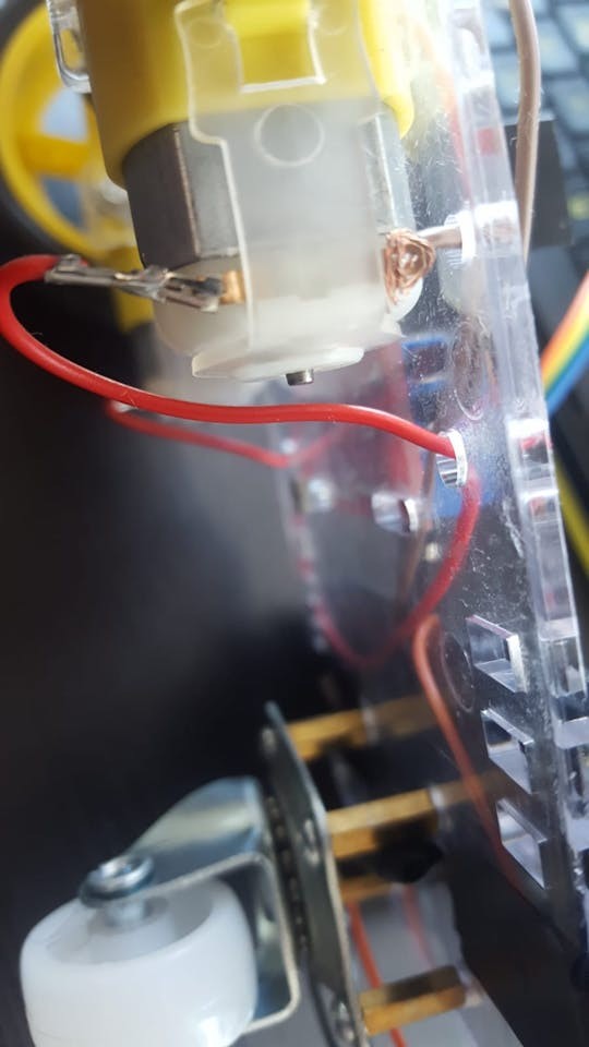
Prepare Components: Gather the main chassis frame, four motor mounting brackets (two for each motor), screws, brass spacers, nuts, motors, an old USB cable, and four jumper wires.
-
Connect Wires to Motors: Attach one wire to each motor pin. Soldering is ideal for a secure connection, but if you don’t have a soldering iron, you can carefully twist the wires around the pins to ensure contact.
-
Prepare USB Cable for Power: Take your spare USB cable and cut off one end, leaving about 20cm (8 inches) of cable length.
-
Expose Power Wires: Carefully strip a few centimeters of the outer cable insulation to reveal the internal wires. You should see 4 or 5 wires inside. We need the black (GND – Ground) and red (Plus – Positive) wires. Strip about 2-4 cm of insulation from the ends of the red and black wires. For a more robust connection, you can twist or solder these to longer, stronger jumper wires.
-
Mount Motors to Chassis: Secure each motor to the chassis frame using the plastic brackets, screws, and nuts. Note the small dot on one side of each motor – this should face inwards, so the dots face each other when both motors are mounted.
- Install Supporting Wheel Spacers: Locate the four small, square-shaped holes at the rear of the chassis frame. Attach the brass spacers to these holes using screws, ensuring the spacers are on the same side of the frame as the motors.
- Mount Supporting Wheel: Attach the nylon supporting wheel to the brass spacers using screws.
- Attach Wheels to Motors: Install the wheels onto each motor shaft. The wheel hubs have a specific shape to match the motor shaft, so align them correctly. You might encounter some resistance, so apply gentle but firm pressure to push the wheels onto the shafts.
- Mount Arduino and Motor Controller: At this stage, you can mount the Arduino Uno and the DC motor controller onto the chassis frame. I used spare screws and nuts from the kit. Use electrical tape to insulate any exposed wires for safety.
Step 2: Wiring the Electronics
With the chassis assembled and components mounted, it’s time to connect everything. Prepare your male-male and female-male jumper wires.
-
Connect Motors to Motor Controller: Connect the wires from the motors to the DC motor controller’s output terminals. For clarity, let’s designate the pins closer to the ground as negative (-) and those closer to the frame as positive (+). The wiring should be as follows:
- OUT1: Left motor (-) GND wire
- OUT2: Left motor (+) wire
- OUT3: Right motor (+) wire
- OUT4: Right motor (-) GND wire
-
Connect Arduino to Motor Controller: Now, connect the Arduino Uno to the DC motor controller using the IN1, IN2, IN3, and IN4 pins. The OUT pins power the motors, while the IN pins send control signals from the Arduino. Female-male jumper wires are ideal here. If you only have male-male, you might need to carefully modify them or solder wires directly to the pins.
- IN1: Arduino Digital Pin 5
- IN2: Arduino Digital Pin 6
- IN3: Arduino Digital Pin 10
- IN4: Arduino Digital Pin 11
-
Connect Bluetooth Module: The Bluetooth module is crucial for wireless control. The HC-06 (or HC-05) module has four pins labeled: VCC (Power), GND (Ground), TXD (Transmit Data), and RXD (Receive Data). Female-male jumper wires will be needed again.
- VCC: Arduino 5V Power
- GND: Arduino GND
- TXD: Arduino Digital Pin 0 (RXD)
- RXD: Arduino Digital Pin 1 (TXD)
Notice that the TXD and RXD pins are cross-connected – the transmit pin of one device connects to the receive pin of the other, allowing data exchange.
-
Connect Piezo Buzzer (Optional): The piezo buzzer adds sound effects to your RC car. It has two legs: a longer Anode (+) and a shorter Cathode (-). While a 330 Ohm resistor is recommended between the buzzer and the Anode to protect it, I skipped it for louder sound. Female-male jumpers are useful here as well.
- Anode (+, longer leg): Arduino Digital Pin 3
- Cathode (-, shorter leg): Arduino GND
-
Powering the Motor Controller: Use the prepared USB cable (red and black wires) to power the DC motor controller.
- Red Wire (+): DC Motor Controller 12V Input
- Black Wire (-): DC Motor Controller GND
-
Powering the System: Connect two USB cables to your power bank. One cable will power the Arduino Uno, and the other will power the DC motor controller (via the USB cable connected in the previous step). Secure the power bank to the chassis using electrical tape or another mounting method. Some power banks have a power button that needs to be switched on to activate the outputs.
- Final Check: Double-check all wiring connections against the diagrams before proceeding to the programming stage.
Step 3: Programming Your Arduino Uno
With the hardware set up, the final step is to upload the code to your Arduino Uno and install the control app on your Android phone.
- Install Arduino IDE: Download and install the Arduino IDE (Integrated Development Environment) from the official Arduino website.
- Configure Arduino IDE: Open the Arduino IDE. Go to “Tools” > “Board:” and select “Arduino Uno.” Then, go to “Tools” > “Port:” and choose the port that your Arduino is connected to. If the “Port” option is grayed out, connect your Arduino to your computer via USB cable. You might need to try different USB ports on your computer until the Arduino is recognized.
-
Upload the Code: You have two options for uploading the code:
a. Download and Open: Download the provided Arduino code file (if available as a separate file), open it in the Arduino IDE, and proceed to upload.
b. Copy and Paste: Open a new file in the Arduino IDE (File > New), copy the code provided below, and paste it into the new file. Click the “Upload” button (arrow icon).Important Note: Disconnect the Bluetooth module’s TX (Digital 1) and RX (Digital 0) wires from the Arduino during code upload. These connections can interfere with the data transfer from your computer to the Arduino. Reconnect them after the upload is complete.
#define in1 5
#define in2 6
#define in3 10
#define in4 11

int state;
int piezo = 3;

void setup() {
  pinMode(in1, OUTPUT);
  pinMode(in2, OUTPUT);
  pinMode(in3, OUTPUT);
  pinMode(in4, OUTPUT);
  pinMode(piezo,OUTPUT);
  Serial.begin(9600);
}

void loop() {
  if (Serial.available() > 0) {
    state = Serial.read();
    Stop();
    switch (state) {
      case 'F': forward(); soundFX(3000.0,30+400*(1+sin(millis()/5000))); break;
      case 'G': forwardleft(); soundFX(3000.0,60); break;
      case 'D': forwardright(); soundFX(3000.0,60); break;
      case 'N': backright(); soundFX(3000.0,30+100*(1+sin(millis()/2500))); break;
      case 'C': backleft(); soundFX(3000.0,30+100*(1+sin(millis()/2500)));
                 soundFX(3000.0,30+100*(1+sin(millis()/2500)));
                 soundFX(3000.0,30+100*(1+sin(millis()/2500)));
                 soundFX(3000.0,30+100*(1+sin(millis()/2500))); break;
      case 'B': back(); soundFX(3000.0,30+200*(1+sin(millis()/2500)));
                 soundFX(3000.0,30+200*(1+sin(millis()/2500)));
                 soundFX(3000.0,30+200*(1+sin(millis()/2500)));
                 soundFX(3000.0,30+200*(1+sin(millis()/2500))); break;
      case 'L': left(); soundFX(3000.0,60);
                 soundFX(3000.0,60);
                 soundFX(3000.0,60);
                 soundFX(3000.0,60); break;
      case 'R': right(); soundFX(3000.0,60);
                 soundFX(3000.0,60);
                 soundFX(3000.0,60);
                 soundFX(3000.0,60); break;
      case 'H': soundFX(3000.0,30+200*(1+sin(millis()/2500)));
                 soundFX(3000.0,60);
                 soundFX(3000.0,30+200*(1+sin(millis()/2500)));
                 soundFX(3000.0,60);
    }
  }
}

void forward() {
  analogWrite(in1, 255);
  analogWrite(in3, 255);
}

void forwardleft() {
  analogWrite(in1, 50);
  analogWrite(in3, 255);
}

void forwardright() {
  analogWrite(in1, 255);
  analogWrite(in3, 50);
}

void back() {
  analogWrite(in2, 255);
  analogWrite(in4, 255);
}

void backright() {
  analogWrite(in2, 50);
  analogWrite(in4, 255);
}

void backleft() {
  analogWrite(in2, 50);
  analogWrite(in4, 50);
}

void left() {
  analogWrite(in4, 255);
  analogWrite(in1, 255);
}

void right() {
  analogWrite(in3, 255);
  analogWrite(in2, 255);
}

void Stop() {
  analogWrite(in1, 0);
  analogWrite(in2, 0);
  analogWrite(in3, 0);
  analogWrite(in4, 0);
}

void soundFX(float amplitude,float period){
  int uDelay=2+amplitude+amplitude*sin(millis()/period);
  for(int i=0;i<200;i++){
  digitalWrite(piezo, HIGH);
  delayMicroseconds(uDelay);
  digitalWrite(piezo, LOW);
  delayMicroseconds(uDelay);
  }
}-
Reconnect Bluetooth and Power: After successful code upload, reconnect the Bluetooth module’s TX and RX wires to the Arduino. Reconnect the USB cable from the Arduino to the power bank.
-
Install Control App: Download the “ArduCar – Arduino RC Car Bluetooth Controller” app from the Google Play Store on your Android phone. Alternatively, you can use other compatible Bluetooth RC car control apps that send matching serial commands, or even develop your own app!
- Start Controlling Your RC Car: Launch the ArduCar app, connect to your Bluetooth module, and start driving your newly built Arduino RC car!
Congratulations on building your own Arduino Uno RC car! Enjoy the fun and explore further modifications and enhancements. If you have any questions or suggestions, please leave them in the comments below.
Step 4: Understanding the Arduino Code and Bluetooth Configuration (Optional)
For those eager to understand the code and delve deeper, let’s break down the Arduino program. This explanation will help you grasp the logic behind controlling your RC car. While this code is inspired by various open-source projects, I’ve simplified it and added the piezo buzzer sound effects.
Arduino code is written in a simplified version of C/C++. If you’re familiar with these languages, you’ll find it recognizable; if not, don’t worry, it’s beginner-friendly. Every Arduino program has two fundamental sections:
-
void setup() { }: This section configures the Arduino pins and runs only once at the start of the program.In our code:
void setup() {
  pinMode(in1, OUTPUT);
  pinMode(in2, OUTPUT);
  pinMode(in3, OUTPUT);
  pinMode(in4, OUTPUT);
  pinMode(piezo, OUTPUT);
  Serial.begin(9600);
}
pinMode(in1, OUTPUT);pinMode()sets the mode of a specific Arduino pin. Here,in1(which we’ve defined as pin 5) is set toOUTPUT, meaning the Arduino will send signals out from this pin to control another component (the motor controller).INPUTwould be used if the pin were to receive data, like from a sensor.pinMode(in2, OUTPUT); pinMode(in3, OUTPUT); pinMode(in4, OUTPUT); pinMode(piezo, OUTPUT);These lines similarly configure pinsin2,in3,in4, andpiezoas output pins.Serial.begin(9600);Serialrefers to serial communication, which is how the Arduino communicates with the Bluetooth module (via Digital pins 0 and 1).Serial.begin(9600)initializes serial communication at a baud rate of 9600 bits per second. This is a common and stable baud rate for Bluetooth modules. Higher baud rates are faster but can be more susceptible to noise. It’s generally best to leave it at 9600 unless you have a specific reason to change it. The Bluetooth module is typically configured to 9600 baud rate by default.
-
void loop() { }: This section contains the main program code that runs repeatedly in a continuous loop, as the name suggests.Before diving into the
loop()section, let’s look at the beginning of the code:#define in1 5 #define in2 6 #define in3 10 #define in4 11 int state; int piezo = 3;#define in1 5The#definedirective creates symbolic constants. Here,in1is defined as a symbolic name for pin number 5 on the Arduino. This makes the code more readable. Instead of remembering that pin 5 controls motor input 1, we can use the more descriptive namein1.#define in2 6,#define in3 10,#define in4 11These lines define symbolic names for Arduino pins 6, 10, and 11, corresponding to motor controller inputsin2,in3, andin4.int state;This line declares an integer variable namedstate. Variables are used to store data that can change during program execution.statewill store the command received from the Bluetooth module.int piezo = 3;This declares an integer variable namedpiezoand initializes it with the value 3. This links thepiezovariable to Arduino pin 3, which is connected to the piezo buzzer.
Now, let’s examine the
loop()section:void loop() { if (Serial.available() > 0) { state = Serial.read(); Stop(); switch (state) { case 'F': forward(); soundFX(3000.0,30+400*(1+sin(millis()/5000))); break; case 'G': forwardleft(); soundFX(3000.0,60); break; case 'D': forwardright(); soundFX(3000.0,60); break; case 'N': backright(); soundFX(3000.0,30+100*(1+sin(millis()/2500))); break; case 'C': backleft(); soundFX(3000.0,30+100*(1+sin(millis()/2500))); break; case 'B': back(); soundFX(3000.0,30+200*(1+sin(millis()/2500))); break; case 'L': left(); soundFX(3000.0,60); break; case 'R': right(); soundFX(3000.0,60); break; case 'H': soundFX(3000.0,30+200*(1+sin(millis()/2500))); break; } } }if (Serial.available() > 0): This line checks if there is any data available to be read from the serial port (Bluetooth module).Serial.available()returns the number of bytes of data waiting to be read. If it’s greater than 0, it means data has been received from the Bluetooth module.state = Serial.read();: If data is available, this line reads the first byte of serial data and stores it in thestatevariable. This byte represents the command sent from your Bluetooth control app (e.g., ‘F’ for forward, ‘L’ for left, etc.).Stop();: This line calls theStop()function, which immediately stops the car’s motors before executing any new command. This ensures that the car responds predictably to each new command.switch (state): This is aswitchstatement, which is used to execute different blocks of code based on the value of thestatevariable.case 'F': forward(); soundFX(...); break;: This is acasewithin theswitchstatement. If thestatevariable is equal to the character ‘F’ (meaning the app sent the “forward” command), theforward()function is called to move the car forward. Then,soundFX(...)is called to play a sound effect.break;exits theswitchstatement after executing the code for this case.- The other
casestatements ('G','D','N','C','B','L','R','H') follow the same pattern, each corresponding to a different command character sent from the app and calling the appropriate motor control function (forwardleft(),forwardright(),backright(),backleft(),back(),left(),right()) and sound effect.
Finally, let’s look at the motor control and sound effect functions defined at the end of the code:
void forward() {
  analogWrite(in1, 255);
  analogWrite(in3, 255);
}

// ... (other motor control functions: forwardleft(), forwardright(), back(), backright(), backleft(), left(), right(), Stop()) ...

void soundFX(float amplitude, float period){
  int uDelay=2+amplitude+amplitude*sin(millis()/period);
  for(int i=0;i<200;i++){
    digitalWrite(piezo, HIGH);
    delayMicroseconds(uDelay);
    digitalWrite(piezo, LOW);
    delayMicroseconds(uDelay);
  }
}
void forward() { ... }: This is an example of a motor control function.voidindicates that the function doesn’t return any value.forward()is the name of the function.analogWrite(in1, 255); analogWrite(in3, 255);:analogWrite()is used to control the speed of the motors. It sends a PWM (Pulse Width Modulation) signal to a specified pin. The value 255 represents the maximum speed (100% duty cycle).in1andin3are set to 255 to make both left and right motors run forward at full speed, resulting in the car moving straight forward. DifferentanalogWrite()values (between 0 and 255) can be used to control motor speed and direction for turning and other movements.- The other motor control functions (
forwardleft(),forwardright(),back(), etc.) use different combinations ofanalogWrite()values on pinsin1,in2,in3, andin4to achieve different car movements. void Stop() { ... }: This function setsanalogWrite()to 0 for all motor control pins, effectively stopping all motors.void soundFX(float amplitude, float period) { ... }: This function generates a sound effect using the piezo buzzer. It takesamplitudeandperiodas parameters to control the sound’s characteristics. It usesdigitalWrite()to rapidly turn the piezo pin HIGH and LOW, creating sound waves. The complex calculation insidedelayMicroseconds()creates a varying frequency sound for a Sci-Fi effect (inspired by Arduino forum examples). You can explore the Arduino forum link provided in the original article for more details on creating different sound effects.
This detailed code explanation should give you a solid understanding of how the Arduino program controls your RC car. Feel free to experiment with the code, modify motor speeds, create new movement patterns, or design your own sound effects!
Bluetooth Module Configuration (Optional)
HC-05 and HC-06 Bluetooth modules typically come pre-configured with default settings like baud rate, name, and password. However, if you wish to customize these settings, you can use the Arduino IDE for configuration. This usually involves temporarily changing the Bluetooth module’s connections and modifying the Arduino code specifically for configuration purposes. It’s also recommended to use voltage dividers (resistors) to protect the Bluetooth module’s data pins, as they operate at 3.3V while the Arduino outputs 5V. Numerous online tutorials detail the Bluetooth module configuration process – a quick search for “HC-06 Bluetooth configuration Arduino” will provide comprehensive guides.
Thank you for following along, and remember to share your own Arduino RC car projects in the comments below!