
Are you fascinated by electronics and programming but feel intimidated to start? Many believe that delving into these fields requires advanced degrees, but that’s a myth. As a car enthusiast, technician, and coding lover, I’ve always been drawn to Arduino. Combined with my childhood dream of building a remote control (RC) car, learning to code and acquiring an Arduino kit presented the perfect opportunity to bring that dream to life.
This guide will walk you through creating an Arduino-based RC car from scratch. No prior experience in programming, Arduino, or electronics is necessary. While some background in these areas might be helpful, these instructions are designed for beginners. You might wonder about using a power bank – they are now very affordable, often cheaper than batteries, reusable, and easily rechargeable. This project uses readily available materials and focuses on the fundamental principles of building an RC car, with detailed code explanations applicable to various other projects. Let’s get started and explore the exciting world of Arduino Remote Control Car Programs!
Parts You’ll Need
Before we begin, gather these materials. I aimed to use common household items and affordable components, reflecting a hobbyist approach. Feel free to adapt and get creative with your own parts!
- Arduino UNO: The brain of our RC car.
- Car Chassis Kit: Includes the base, wheels, and motors.
- Jumper Wires (Male-Male & Female-Male): For connecting components.
- Electrical Insulation Tape: For securing connections and insulation.
- Bluetooth Module (HC-06 or HC-05): Enables wireless control via your phone.
- DC Motor Controller (L298N): To control the car’s motors.
- Power Bank (with 2 USB outputs): To power the car.
- Piezo Buzzer: For optional sound effects.
- Android Mobile Phone: To control the car using a Bluetooth app.
- PC with Arduino IDE: To program the Arduino.
- ArduCar – Arduino RC Car Bluetooth Controller App: (Or any compatible Bluetooth RC car control app).
Step 1: Assembling the Car Chassis
Let’s start by putting together the car’s base. If you bought a chassis kit, it likely came with instructions. If not, follow these general steps:
- Prepare the Components: Gather the chassis base, motor mounting brackets (usually 4 small plastic pieces, two for each motor), screws, brass spacers, nuts, motors, an old USB cable, and jumper wires.
- Connect Wires to Motors: Attach a wire to each motor pin. Soldering is ideal, but if you don’t have a soldering iron, you can twist the wires securely onto the pins.
- Prepare the USB Cable for Power: Take an old USB cable and cut off one end, leaving about 20cm (8 inches) of cable.
- Strip the USB Cable: Carefully strip a few centimeters of the outer cable covering to expose the inner wires. You should see 4 or 5 wires, but we only need the black (GND – Ground) and red (Plus – Positive) wires. Strip about 2-4cm of insulation from the ends of the red and black wires. You can reinforce these connections by twisting or soldering them to longer, stronger jumper wires for better durability.
Image showing a stripped USB cable revealing red and black wires, essential for powering the Arduino remote control car program.
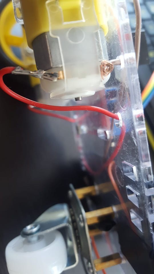
- Mount the Motors: Attach the motors to the chassis frame using the plastic brackets, screws, and nuts. Note the small “dot” on one side of each motor; this dot should face inwards when mounting the motors, so they face each other once installed. This orientation is important for consistent motor direction in your Arduino RC car program.
- Install the Supporting Wheel: Locate the four small, square-shaped holes at the end of the chassis frame. Use brass spacers and screws to attach them to these holes, ensuring the spacers are on the same side of the frame as the motors.
- Mount the Nylon Wheel: Attach the nylon supporting wheel to the brass spacers using screws.
- Attach the Wheels to Motors: Push the wheels onto the motor shafts. Note the shape inside the wheel hub; align it correctly with the motor shaft. This might require some force, but be gentle and persistent.
- Mount Arduino and Motor Controller: Position the Arduino module and DC motor controller on the chassis frame. Use spare screws and nuts from the kit to secure them. Insulate any exposed wires with electrical tape for safety.
Step 2: Wiring the Electronics
With the chassis assembled and components mounted, it’s time to connect everything. Prepare your male-male and female-male jumper wires.
-
Connect Motors to Motor Controller: Attach the wires from the motors to the DC motor controller’s OUT terminals. Assuming the pins closer to the ground are negative (-) and those closer to the frame are positive (+), connect them as follows:
- OUT1: Left motor (-) GND cable
- OUT2: Left motor (+) cable
- OUT3: Right motor (+) cable
- OUT4: Right motor (-) GND cable
-
Connect Arduino to Motor Controller: Now, connect the Arduino to the motor controller using the IN pins. You’ll be sending control signals from the Arduino to the controller through these pins. Female-male jumpers are ideal, but you can modify male-male jumpers or solder wires if needed.
- IN1: Arduino Digital Pin 5
- IN2: Arduino Digital Pin 6
- IN3: Arduino Digital Pin 10
- IN4: Arduino Digital Pin 11
-
Connect Bluetooth Module: The Bluetooth module enables wireless control. It typically has 4 pins labeled VCC, GND, TXD, and RXD. Use female-male jumpers again.
- VCC: Arduino 5V (Power)
- GND: Arduino GND (Ground)
- TXD: Arduino Digital Pin 0 (RXD – Receive Data)
- RXD: Arduino Digital Pin 1 (TXD – Transmit Data)
Notice that the TXD and RXD pins are cross-connected for data exchange between the Arduino and Bluetooth module.
-
Connect Piezo Buzzer (Optional): The piezo buzzer adds sound effects. It has two legs: a longer Anode (+) and a shorter Cathode (-). While a 330 Ohm resistor is recommended for sensitive buzzers, it’s often omitted for louder sound. Female-male jumpers are helpful here.
- Anode (+) (Longer leg): Arduino Digital Pin 3
- Cathode (-) (Shorter leg): Arduino GND (Ground)
-
Powering the Motor Controller: Take the prepared USB cable (red and black wires) and connect them to the DC motor controller’s power input:
- Red cable (+): 12V
- Black cable (-): GND
-
Powering the Circuit: Finally, connect two USB cables to your power bank. One cable connects the power bank to the Arduino board (for Arduino power), and the other connects the power bank to the DC motor controller (for motor power). Mount the power bank onto the chassis using electrical tape or another secure method. Some power banks have a power button that you may need to switch on.
With all parts wired, we’re ready to program the Arduino and control our RC car!
Step 3: Programming the Arduino
Now for the exciting part – bringing your RC car to life with code! You’ll need to upload the Arduino remote control car program to the Arduino board.
- Install Arduino IDE: Download and install the Arduino IDE (Integrated Development Environment) from the official Arduino website (https://www.arduino.cc/).
- Configure Arduino IDE: Open the Arduino IDE. Go to “Tools” > “Board:” and select your Arduino board (usually “Arduino UNO”). Then, go to “Tools” > “Port:” and select the port your Arduino is connected to. If the “Port” option is greyed out, connect your Arduino to your computer via USB; it should become available. You might need to try different USB ports on your computer.
-
Upload the Code: You have two options for uploading the Arduino code:
- Download and Open: Download the provided Arduino code file (if available). Open it in the Arduino IDE and proceed to upload.
- Copy and Paste: Copy the code provided below. In the Arduino IDE, go to “File” > “New,” paste the code into the new sketch, and then click the “Upload” button (arrow icon).
Important: Disconnect the Bluetooth module’s DIGITAL 0 (RX) and DIGITAL 1 (TX) wires from the Arduino before uploading the code. Leaving them connected can interfere with the upload process.
Here’s the Arduino code for your RC car:
#define in1 5
#define in2 6
#define in3 10
#define in4 11
int state;
int piezo = 3;

void setup() {
  pinMode(in1, OUTPUT);
  pinMode(in2, OUTPUT);
  pinMode(in3, OUTPUT);
  pinMode(in4, OUTPUT);
  pinMode(piezo,OUTPUT);
  Serial.begin(9600);
}

void loop() {
  if (Serial.available() > 0) {
    state = Serial.read();
    Stop();
    switch (state) {
      case 'F':
        forward();
        soundFX(3000.0,30+400*(1+sin(millis()/5000)));
        break;
      case 'G':
        forwardleft();
        soundFX(3000.0,60);
        break;
      case 'D':
        forwardright();
        soundFX(3000.0,60);
        break;
      case 'N':
        backright();
        soundFX(3000.0,30+100*(1+sin(millis()/2500)));
        break;
      case 'C':
        backleft();
        soundFX(3000.0,30+100*(1+sin(millis()/2500)));
        soundFX(3000.0,30+100*(1+sin(millis()/2500)));
        soundFX(3000.0,30+100*(1+sin(millis()/2500)));
        soundFX(3000.0,30+100*(1+sin(millis()/2500)));
        break;
      case 'B':
        back();
        soundFX(3000.0,30+200*(1+sin(millis()/2500)));
        soundFX(3000.0,30+200*(1+sin(millis()/2500)));
        soundFX(3000.0,30+200*(1+sin(millis()/2500)));
        soundFX(3000.0,30+200*(1+sin(millis()/2500)));
        break;
      case 'L':
        left();
        soundFX(3000.0,60);
        soundFX(3000.0,60);
        soundFX(3000.0,60);
        soundFX(3000.0,60);
        break;
      case 'R':
        right();
        soundFX(3000.0,60);
        soundFX(3000.0,60);
        soundFX(3000.0,60);
        soundFX(3000.0,60);
        break;
      case 'H':
        soundFX(3000.0,30+200*(1+sin(millis()/2500)));
        soundFX(3000.0,60);
        soundFX(3000.0,30+200*(1+sin(millis()/2500)));
        soundFX(3000.0,60);
    }
  }
}

void forward() {
  analogWrite(in1, 255);
  analogWrite(in3, 255);
}

void forwardleft() {
  analogWrite(in1, 50);
  analogWrite(in3, 255);
}

void forwardright() {
  analogWrite(in1, 255);
  analogWrite(in3, 50);
}

void back() {
  analogWrite(in2, 255);
  analogWrite(in4, 255);
}

void backright() {
  analogWrite(in2, 50);
  analogWrite(in4, 255);
}

void backleft() {
  analogWrite(in2, 50);
  analogWrite(in4, 50);
}

void left() {
  analogWrite(in4, 255);
  analogWrite(in1, 255);
}

void right() {
  analogWrite(in3, 255);
  analogWrite(in2, 255);
}

void Stop() {
  analogWrite(in1, 0);
  analogWrite(in2, 0);
  analogWrite(in3, 0);
  analogWrite(in4, 0);
}

void soundFX(float amplitude,float period){
  int uDelay=2+amplitude+amplitude*sin(millis()/period);
  for(int i=0;i<200;i++){
    digitalWrite(piezo, HIGH);
    delayMicroseconds(uDelay);
    digitalWrite(piezo, LOW);
    delayMicroseconds(uDelay);
  }
}- Reconnect and Power Up: Once the code is uploaded, reconnect the Bluetooth module’s DIGITAL 0 (RX) and DIGITAL 1 (TX) pins. Reconnect the USB cable from the Arduino to the power bank to power up the car.
- Install and Use the Control App: Download the “ArduCar – Arduino RC Car Bluetooth Controller” app (or your chosen compatible app) from the Google Play Store onto your Android phone. Launch the app, connect to your car’s Bluetooth module, and start driving!
Congratulations! You’ve built your own Arduino-controlled RC car. Enjoy driving it around and experimenting with the code to customize its behavior and add new features.
Step 4: Understanding the Arduino Code
For those eager to understand the Arduino code behind your RC car, let’s break it down. The Arduino IDE uses a simplified version of C/C++.
Every Arduino program has two main sections:
-
void setup() { }: This section runs only once when the Arduino starts. It’s used to configure pins and initialize settings.void setup() { pinMode(in1, OUTPUT); pinMode(in2, OUTPUT); pinMode(in3, OUTPUT); pinMode(in4, OUTPUT); pinMode(piezo,OUTPUT); Serial.begin(9600); }pinMode(in1, OUTPUT);and similar lines set the specified pins (in1, in2, in3, in4, piezo) asOUTPUT. This means the Arduino will send signals out from these pins to control other components (like the motor controller and buzzer).Serial.begin(9600);initializes serial communication at a baud rate of 9600. This is the speed at which data is transmitted and received via the Bluetooth module. 9600 is a common and reliable baud rate for Bluetooth communication.
-
void loop() { }: This section runs repeatedly in a continuous loop as long as the Arduino is powered. This is where the main control logic of your Arduino remote control car program resides.void loop() { if (Serial.available() > 0) { state = Serial.read(); Stop(); switch (state) { // ... (cases for different commands) ... } } }if (Serial.available() > 0): This checks if there is any data available to be read from the serial port (i.e., from the Bluetooth module).state = Serial.read();: If data is available, it reads the incoming byte and stores it in thestatevariable. Thisstatevariable will hold the command sent from your Bluetooth control app.Stop();: This calls theStop()function to ensure the car stops before executing a new command.switch (state) { ... }: Thisswitchstatement checks the value of thestatevariable and executes different functions based on the received command character.
-
Variable Definitions: At the beginning of the code, you’ll find these lines:
#define in1 5
#define in2 6
#define in3 10
#define in4 11
int state;
int piezo = 3;
#define in1 5: This is a preprocessor directive that definesin1as a symbolic name for digital pin 5. Similarly,in2,in3, andin4are defined for pins 6, 10, and 11 respectively. This makes the code more readable, as you can use names likein1instead of directly using pin numbers.int state;: Declares an integer variable namedstate. This variable will store the command received from the Bluetooth module.int piezo = 3;: Declares an integer variable namedpiezoand initializes it to 3. This associates the piezo buzzer with digital pin 3.
-
Motor Control Functions: The code includes functions to control the motors:
forward(),back(),left(),right(),forwardleft(),forwardright(),backleft(),backright(), andStop().
These functions use
analogWrite(pin, speed)to control the speed and direction of the motors.analogWrite()sends a PWM (Pulse Width Modulation) signal to the motor controller, effectively controlling the voltage supplied to the motors and thus their speed. Thespeedvalue ranges from 0 (stopped) to 255 (full speed). -
Sound Effects Function: The
soundFX()function generates simple sound effects using the piezo buzzer.void soundFX(float amplitude,float period){ int uDelay=2+amplitude+amplitude*sin(millis()/period); for(int i=0;i<200;i++){ digitalWrite(piezo, HIGH); delayMicroseconds(uDelay); digitalWrite(piezo, LOW); delayMicroseconds(uDelay); } }This function creates a sound by rapidly turning the piezo buzzer on and off (
digitalWrite(piezo, HIGH);anddigitalWrite(piezo, LOW);) at a frequency determined by theamplitudeandperiodparameters. The formula insideuDelaycreates a varying delay, resulting in a somewhat Sci-Fi-like sound effect.
This code provides a basic yet functional program for your Arduino remote control car. Feel free to experiment with the code, modify motor speeds, create new movement patterns, or design more complex sound effects to enhance your project!
Bluetooth Module Configuration (Optional)
HC-05 and HC-06 Bluetooth modules typically come pre-configured with default settings (like baud rate, name, and password). However, if you need to customize these settings, you can configure them using the Arduino IDE. This usually involves connecting the Bluetooth module to different Arduino pins temporarily and using specific Arduino code for configuration. Remember that Bluetooth modules often operate at 3.3V logic levels, while Arduino’s default output is 5V. Using resistors for voltage division on the data lines (TX and RX) is recommended to protect the Bluetooth module during configuration if needed. Numerous online tutorials detail the Bluetooth module configuration process if you wish to explore this further.
Thank you for following this guide. We hope you have a blast with your DIY Arduino Remote Control Car! Share your projects and any questions in the comments below.